I wanted a power monitor with high accuracy and fast update speed, but could not find a solution that I liked so I set out to design my own.
Using the ATM90E32 I made a 3-channel voltage/current and power sensor with high accuracy and very fast update speed.
Specifications:
- Input voltage: 90VAC – 250VAC
- Power consumtion: <1W
- voltage measurement accuracy: 0.1%
- Measuring current range: 5mA -> 16A
- Current measurement accuracy: 0.5% +-5mA (pf=1)
- update speed 0.1s – 0.2s (esphome bottleneck)
Some improvements that might be implemented in a new revision:
- Better accuracy when measuring a load with a bad power factor and high frequency noise.
Currently capacitive loads have a current measuring offset causing inaccuracies.
This is most noticeable when only a capacitor is attached, this will cause the meter to measure a slight negative power value.
This will most likely be solved by using shunts instead of current coils. - Smaller footprint.
using different components and changing the layout could significantly reduce the overall board size while keeping the same specs. The board might also need to be changed to 4 layers or use 2oz copper to achieve this. - better flexibility.
with jumpers and different layout it should be possible to give a choice of how to measure power. this could also enable the possibility to measure 3phase power. - add new functionality.
The ability to use a small screen and use an esp32 instead of an esp8266 can be easily implemented in a new revision.
Design
Power supply
The power from the board is supplied by a very small 230V->3.3V SMPS module.
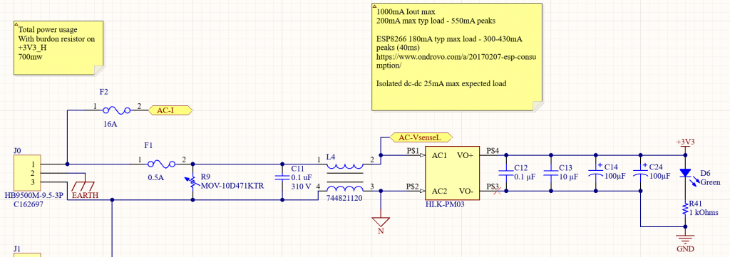
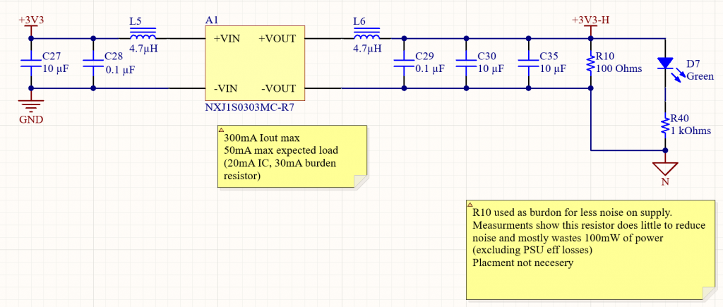
A second Isolated 3.3V power rail is created with a special isolated DC-DC converter.
The secondary 3.3V rail is referenced to one side of the 230VAC.
This is done to achieve 2 goals.
- Isolate the esp8266/esp32 from 230VAC.
This allows the USB connector to still be used when the device is connected to 230V
And when an esp8266/esp32 is used with an external antenna this antenna would also be live with mains voltage if not isolated. this could cause mayor safety concerns. - Keep power consumption low.
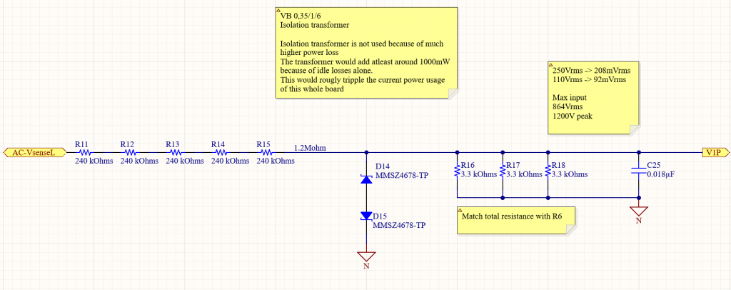
If the power measuring IC would also be Isolated from the mains voltage I would need to use a small transformer to step down the voltage and isolate it. Even the smallest low power 230VAC trafo’s had a standby power consumption of around 1W, this transformer would consume more power than the whole rest of the board just to step down and isolate the voltage. That’s why the power measuring IC GND is referenced to the 230VAC. Stepping the voltage down for the measurment is done with a simple voltage divider.
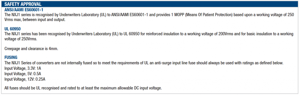
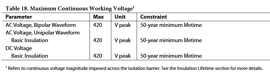
The isolated DC-DC converter is also specially chosen to handle 320V peak continuously.
Most isolated DC-DC converters are only rated to withstand 1000V for a minute but will break down over time if a large voltage difference is present
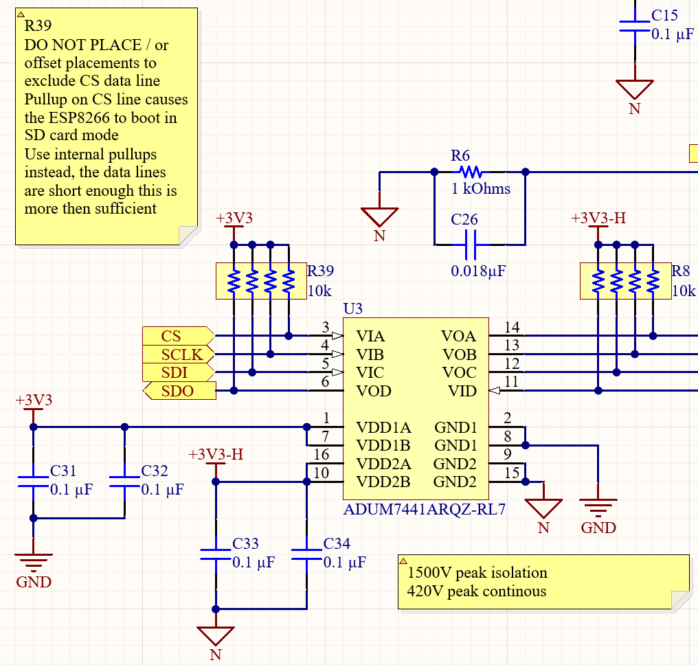
Digital isolation
The power supply isolation also posed a problem for digital communication.
For this, I used a quad-channel capacitive isolator, which allows high-speed communication with a high degree of isolation.
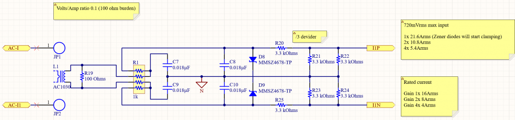
Current measurement
The current is measured using a current transformer on each channel.
The input stage consists of a dual stage low pass filter, Zener diodes to clamp current spikes, and a resistor voltage divider to set the max measured current to 21.6Arms.